2025-2026
Endurance & [BETTER NAME PENDING]
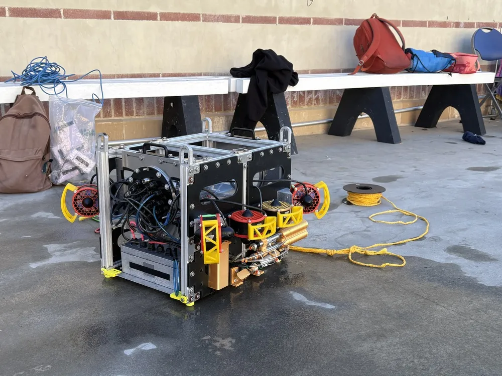
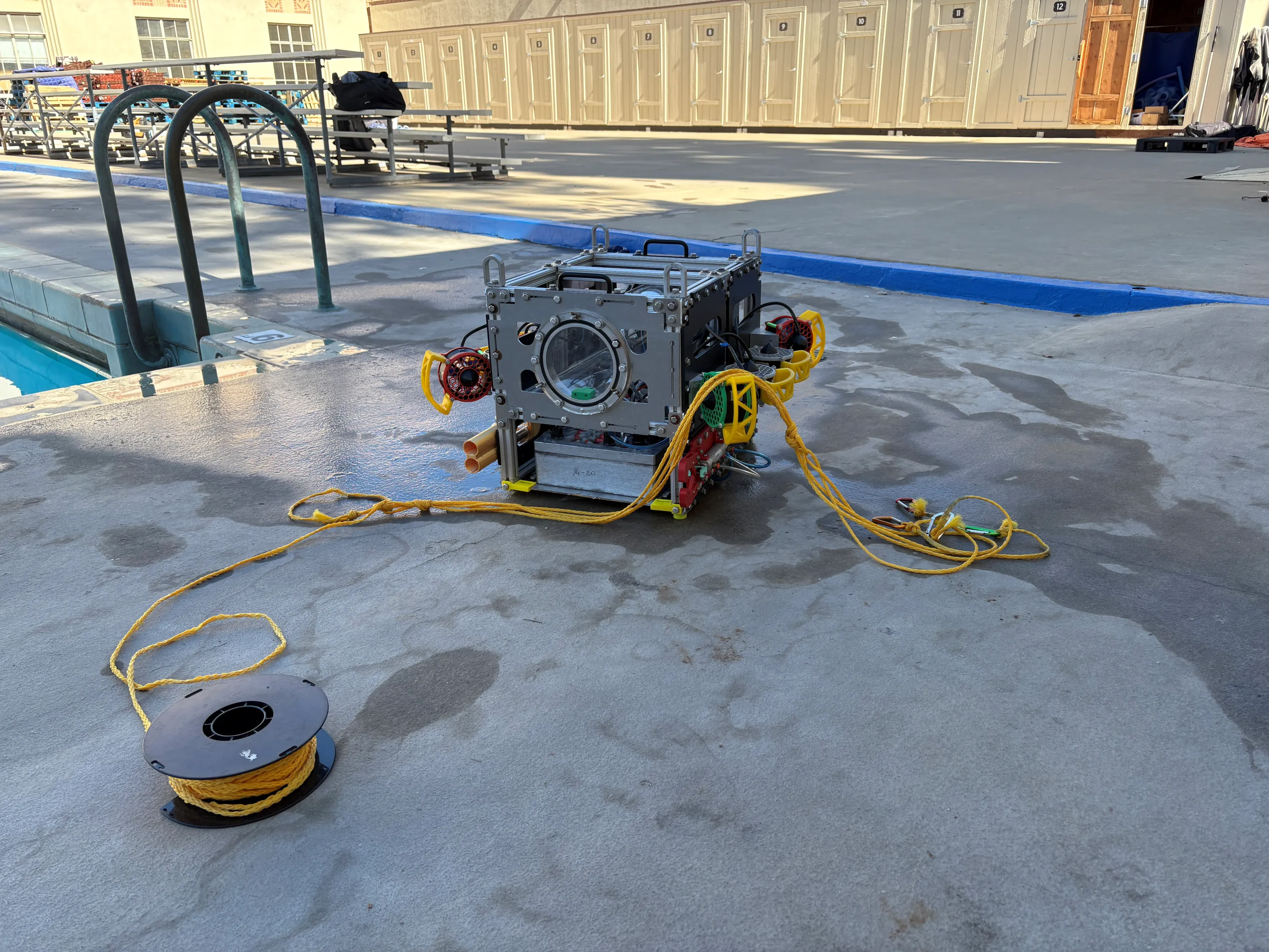
The 2025-2026 season is Bruin Underwater Robotics (BUR)’s third year competing in Robosub, as well as our third year designing autonomous robots in general. We had two goals this year: (i) improve our existing robot, and (ii) pursue new design challenges as a club. For the first objective, we chose to reuse our existing robot and software systems from the Robosub 2025. For the second objective, we opted to design & build a second robot this year, with the goal of entering it into the competition.
With regards to the first goal, several improvements have been made to the bot's pneumatic end effectors, electrical systems, and software systems, although the overall architecture remains similar to last year. With regards to the second goal, although our second robot has been fully designed and partially assembled, we will not be competing with it this year; nevertheless, several aspects of its design are described below!
With regards to the first goal, several improvements have been made to the bot's pneumatic end effectors, electrical systems, and software systems, although the overall architecture remains similar to last year. With regards to the second goal, although our second robot has been fully designed and partially assembled, we will not be competing with it this year; nevertheless, several aspects of its design are described below!
Subsystems
Mechanical: Chassis
Goals
The goals for the Robosub 2026 competition is to continue to compete with the previous design from 2025 with minor improvements alongside a new smaller AUV specifically for mobility based tasks. We decided to continue with the previous chassis to maintain continuity for the software team to make improvements. The primary chassis was designed with reliability and optimization as the top priorities, and as such it remained operable after the 2025 robosub competition. The primary change made to the previous design was renewing 3D printed parts to ensure reliability going forward and experimenting with a double piston flange seal.
The smaller companion AUV was started to maintain club growth as well as tackle mobility challenges. Primary design considerations were utilizing existing stock material and ease of hardware and software integration, while optimizing mobility. Ease of integration is an important consideration since the software subteams priority remained the large AUV.
The smaller companion AUV was started to maintain club growth as well as tackle mobility challenges. Primary design considerations were utilizing existing stock material and ease of hardware and software integration, while optimizing mobility. Ease of integration is an important consideration since the software subteams priority remained the large AUV.
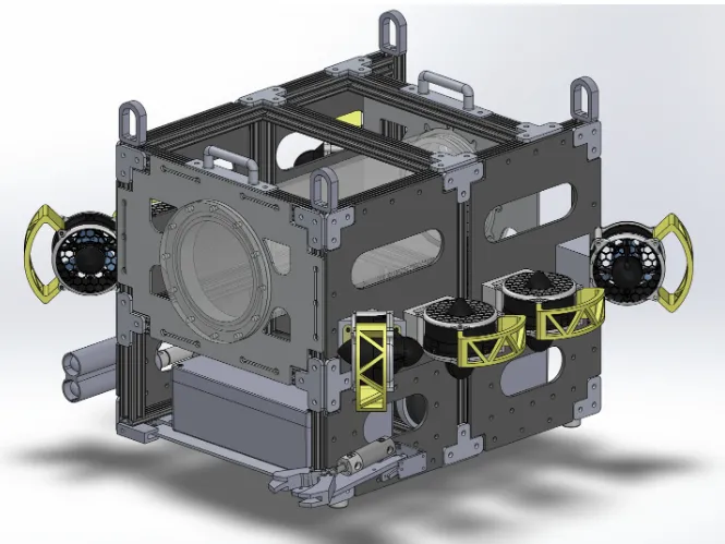
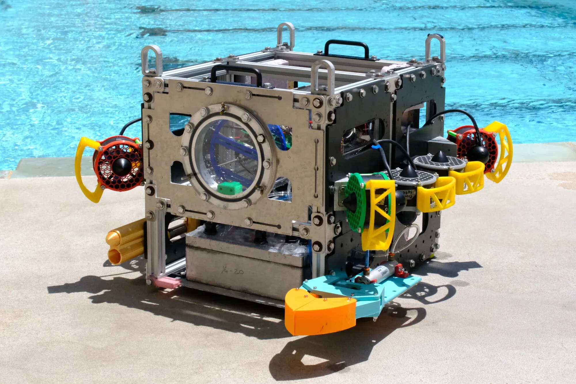
Endurance, our 2025 AUV
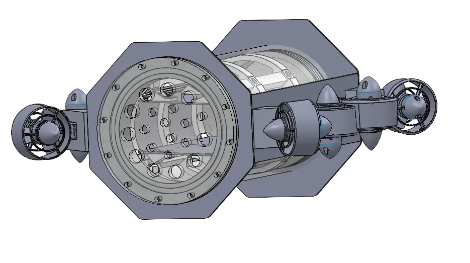
[BETTER NAME PENDING], our smaller AUV
Frame, Slide-Out Panels, and Buoyancy
The large AUV is made of an aluminum t-bar frame with high-density polyethylene panels (HDPE) and aluminum brackets, making the main shell of our AUV extremely rigid. To account for this rigidity in structure, the frame was designed with lots of internal space for different potential additions. External attachment points were also left on the HDPE panels to allow for the addition of any unforeseen components needed on the outside of the AUV as well.
The large AUV utilizes battery and pneumatic boxes housed within the frame. To ensure accessibility the battery and pneumatic boxes are mounted on aluminum panels with 3D-printed rails that allow them to slide within the aluminum t-bar frame, giving us easy access to both boxes without requiring a large disassembly of the AUV. Estimating our center of buoyancy was also a huge consideration when designing our AUV and influenced where our battery and pneumatic boxes would lie compared to the electronics bay.
The small AUV has lower requirements for components since it does not have to house divetops or a battery box. The frame was simplified to HDPE side panels connected to aluminum endcaps via aluminum brackets. This design minimized size and simplified manufacturing, however, length was preserved to maintain distance between thrusters for optimal mobility.
For the smaller AUV, the weight is centered within the electronics bay since there are no external boxes. This simplified buoyancy estimation, since buoyancy would be centered as long as the design centered the e-bay.
The large AUV utilizes battery and pneumatic boxes housed within the frame. To ensure accessibility the battery and pneumatic boxes are mounted on aluminum panels with 3D-printed rails that allow them to slide within the aluminum t-bar frame, giving us easy access to both boxes without requiring a large disassembly of the AUV. Estimating our center of buoyancy was also a huge consideration when designing our AUV and influenced where our battery and pneumatic boxes would lie compared to the electronics bay.
The small AUV has lower requirements for components since it does not have to house divetops or a battery box. The frame was simplified to HDPE side panels connected to aluminum endcaps via aluminum brackets. This design minimized size and simplified manufacturing, however, length was preserved to maintain distance between thrusters for optimal mobility.
For the smaller AUV, the weight is centered within the electronics bay since there are no external boxes. This simplified buoyancy estimation, since buoyancy would be centered as long as the design centered the e-bay.
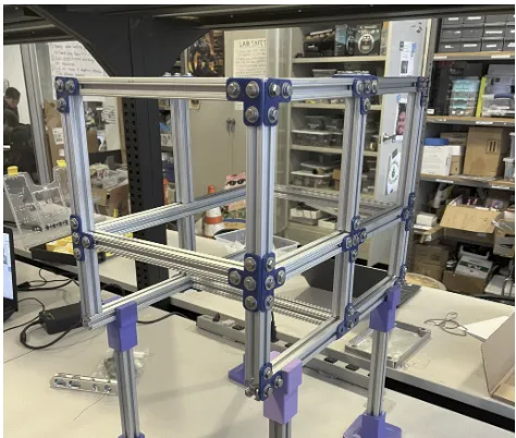
Aluminum T-bar frame
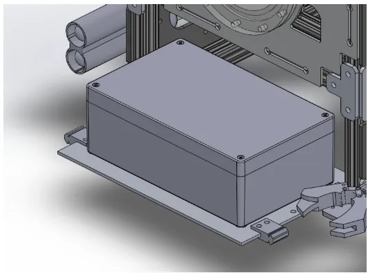
Our pneumatics box slide-out panel
Electronics Bay
The electronics bay of both AUVs utilize an acrylic tube sealed with aluminum flanges fitted with o-rings. The ebays are mounted by its flange directly onto the frame using large aluminum plates. These plates created a rigid structure that gave us a secure, consistent mounting point.
For the small AUV utilizing the same acrylic stock greatly increased the size of the overall design. The smaller AUV is intended to take on less tasks and thus has a lower demand for hardware housing. The stock could not be shortened too far or the reduced spacing between vectored thrusters would reduce Yaw control, thus there was extra space in the ebay. This space was utilized to house the batteries; removing the need for a battery box. In this way even though the same size ebay stock was utilized for both AUV the spacing was optimized to still overall reduce the size of the smaller AUV.
For the small AUV utilizing the same acrylic stock greatly increased the size of the overall design. The smaller AUV is intended to take on less tasks and thus has a lower demand for hardware housing. The stock could not be shortened too far or the reduced spacing between vectored thrusters would reduce Yaw control, thus there was extra space in the ebay. This space was utilized to house the batteries; removing the need for a battery box. In this way even though the same size ebay stock was utilized for both AUV the spacing was optimized to still overall reduce the size of the smaller AUV.
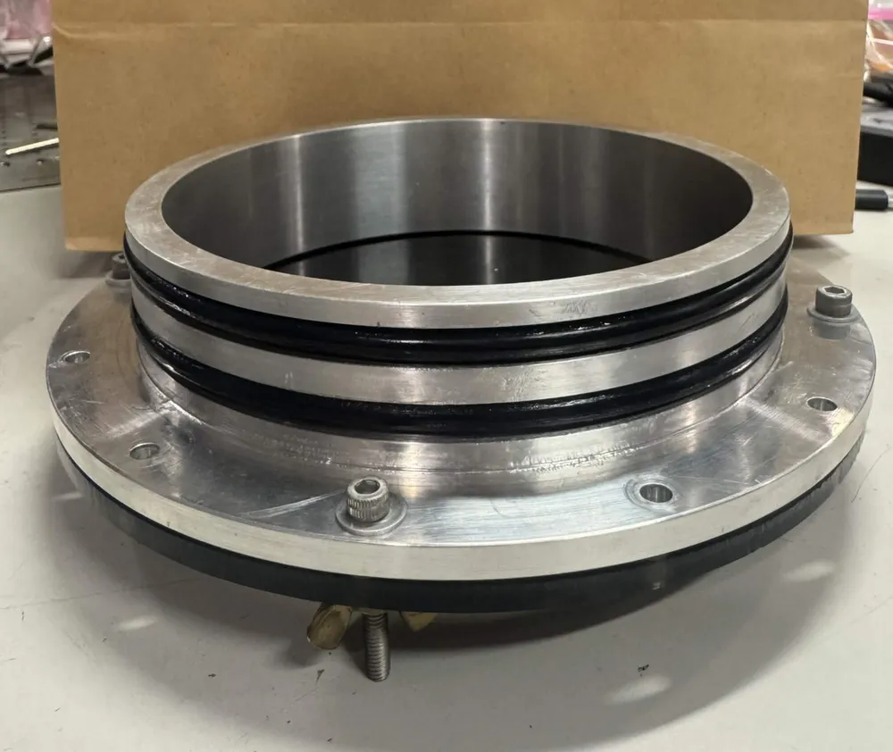
Our endcap
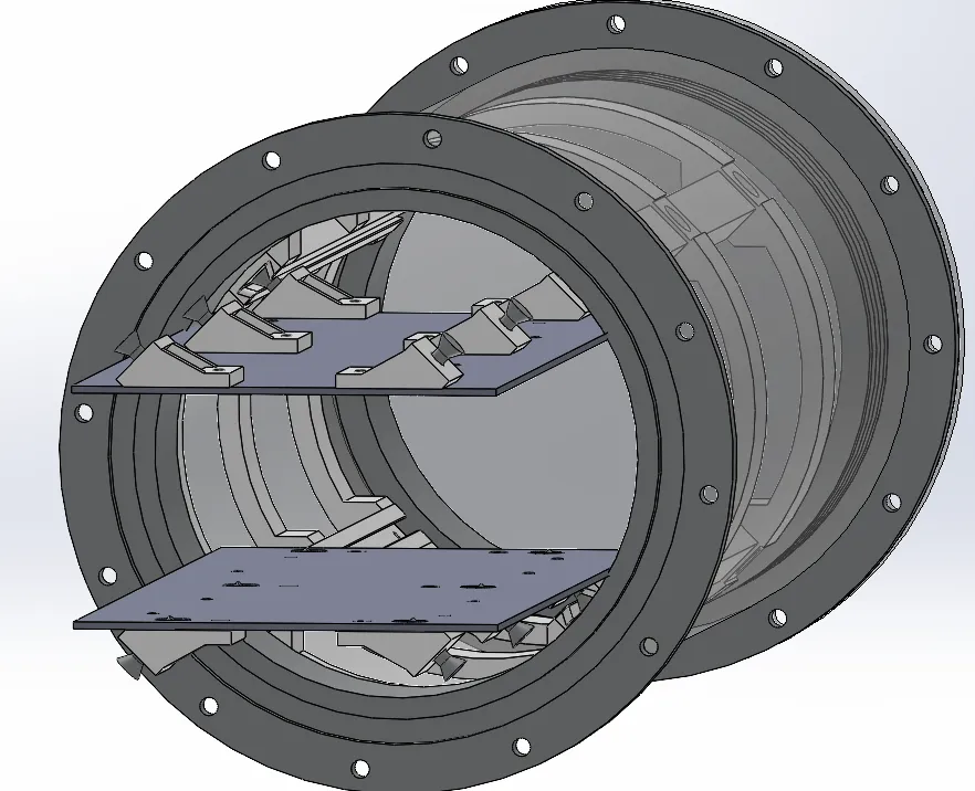
Small AUV electronics bay assembly
Hardware Mounting
To mount our electrical devices in the large AUV, we used a series of parallel vertical plates. All of our cables still route outside the electronics bay through one of our acrylic end caps and are sealed using cordgrips. The 3D printed endcaps experienced fatigue since the previous competition, and were replaced with new endcaps printed with improved strength settings to limit future fatigue.
In the small AUV the electronics housing was redesigned to optimize accessibility. The hardware is mounted on 2 acrylic plates secured to a rail system so that they can be slid in and out of the ebay without having to remove the entire housing structure. The structure attaches to the ebay via 3 structural loops that disperse the load, limiting fatigue of 3D printed components. Without an external battery box or diveops, the smaller AUV has fewer external cables. The thrusters, ethernet, and depth sensor still require external cables which are fed through the acrylic endcap of the ebay.
In the small AUV the electronics housing was redesigned to optimize accessibility. The hardware is mounted on 2 acrylic plates secured to a rail system so that they can be slid in and out of the ebay without having to remove the entire housing structure. The structure attaches to the ebay via 3 structural loops that disperse the load, limiting fatigue of 3D printed components. Without an external battery box or diveops, the smaller AUV has fewer external cables. The thrusters, ethernet, and depth sensor still require external cables which are fed through the acrylic endcap of the ebay.
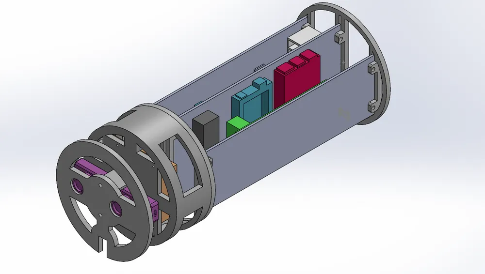
Small AUV electronics bay internals
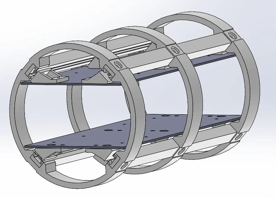
Small AUV electronics bay mounting system
Mechanical: Dive Operations
Torpedoes
Similar to last year, this year we decided to use pneumatics to operate the torpedoes, arm, and dropper. Our system consists of a paintball air tank connected to four solenoid valves that control the flow of air to the 4 actuators. To ensure that the system was safe, we incorporated a vented ball valve, 2 relief valves, and a pressure regulator to keep our operating pressure below the maximum pressure rating of the individual components. Our solenoids were housed in an adjacent aluminum box.
For our torpedoes, we used a double-barrel design utilizing two linear pneumatic actuators. Our 3D printed torpedoes were printed with 80% infill to match water density for neutral buoyancy. Additionally, the torpedoes feature knobs to slide along guiding rails inside the barrels, ensuring the the torpedo launches straight.
For our torpedoes, we used a double-barrel design utilizing two linear pneumatic actuators. Our 3D printed torpedoes were printed with 80% infill to match water density for neutral buoyancy. Additionally, the torpedoes feature knobs to slide along guiding rails inside the barrels, ensuring the the torpedo launches straight.
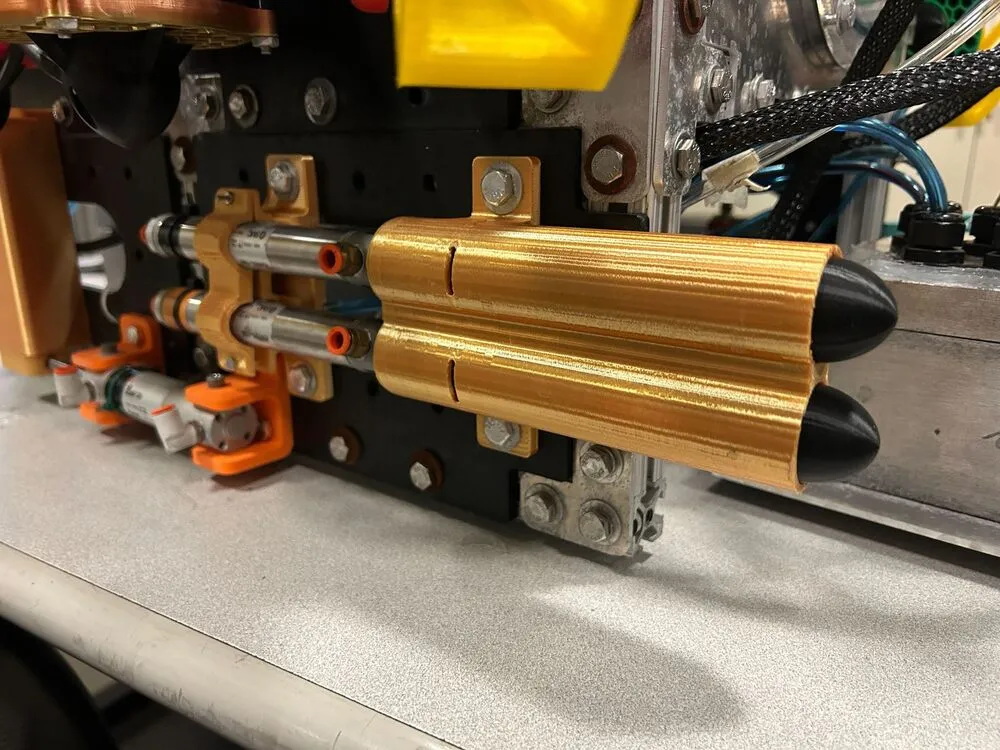
A closeup of our torpedoes
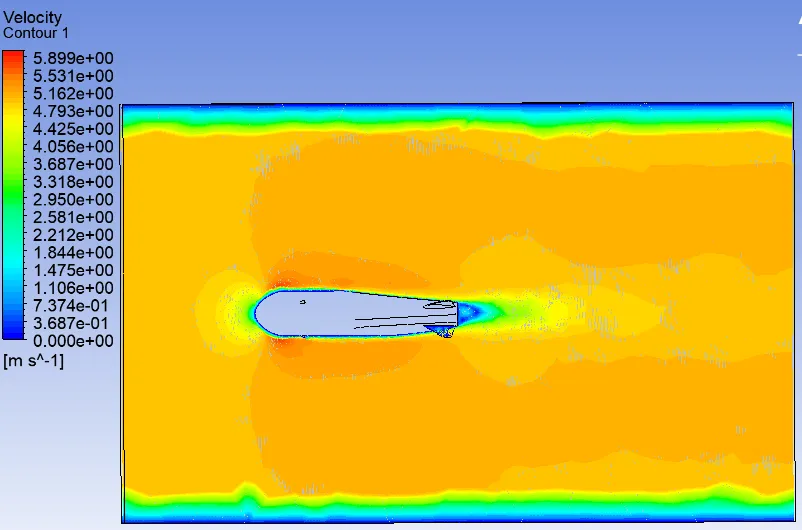
Velocity profile of fluid around the torpedo
The torpedo designs were optimized using our torpedo test rig, which mounts an exact replica of our launcher onto a variable platform. A series of underwater test fires allowed us to optimize the proper launch angle and positioning of our torpedo launcher on our AUV.
In addition, we simulated our torpedo designs using ANSYS to see if our in person findings agreed with the stresses and velocities shown using simulation. Several different nose and fin shapes were proposed. For each design, CFD analysis was performed to analyze the velocity profile and drag coefficient, then a simulation was run to represent a torpedo being shot into still water. One torpedo design appeared to have the best results and was selected as a final design.
In addition, we simulated our torpedo designs using ANSYS to see if our in person findings agreed with the stresses and velocities shown using simulation. Several different nose and fin shapes were proposed. For each design, CFD analysis was performed to analyze the velocity profile and drag coefficient, then a simulation was run to represent a torpedo being shot into still water. One torpedo design appeared to have the best results and was selected as a final design.
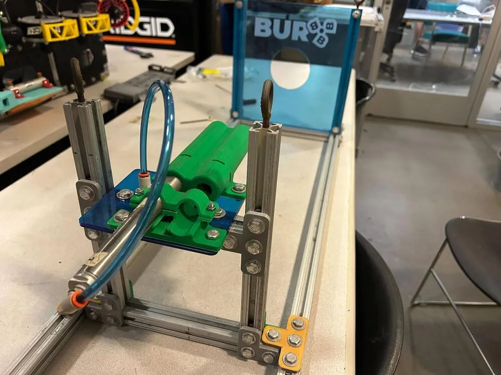
Our torpedo test rig
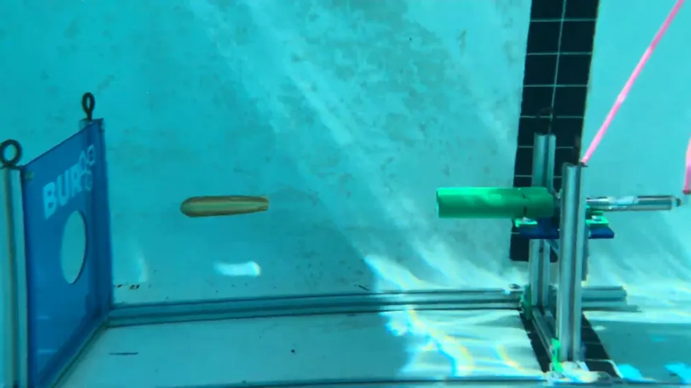
An underwater launch with our test rig
Arm
Our arm design features a completely redesigned four bar linkage system driven by a linear pneumatic actuator, designed to produce a much smoother and more reliable actuation compared to previous years’ designs. We scaled our linkages to balance and offer greater mechanical advantage, a wider jaw opening, and more consistent torque at all positions. In order to achieve strength in the system, the linkages are mounted through the claws to better protect and house them.
We redesigned our claw profiles to match the new mechanism, iterating through a number of shapes and increasing the surface area significantly. We printed our grippers using TPU so they can to deform around objects, thereby grasping them more reliably and tightly. As a result, our claw profiles are now much more adept for grabbing and holding a diverse variety of components, including irregular shapes and sizes.
Lastly, this year we introduced a new mounting solution, pivoting the claw 90 degrees and allowing for easier access to the target objects. We emphasized a simple and secure design that was mounted closely onto the chassis, thereby maximizing stability and limiting the moments on the bot.
We redesigned our claw profiles to match the new mechanism, iterating through a number of shapes and increasing the surface area significantly. We printed our grippers using TPU so they can to deform around objects, thereby grasping them more reliably and tightly. As a result, our claw profiles are now much more adept for grabbing and holding a diverse variety of components, including irregular shapes and sizes.
Lastly, this year we introduced a new mounting solution, pivoting the claw 90 degrees and allowing for easier access to the target objects. We emphasized a simple and secure design that was mounted closely onto the chassis, thereby maximizing stability and limiting the moments on the bot.
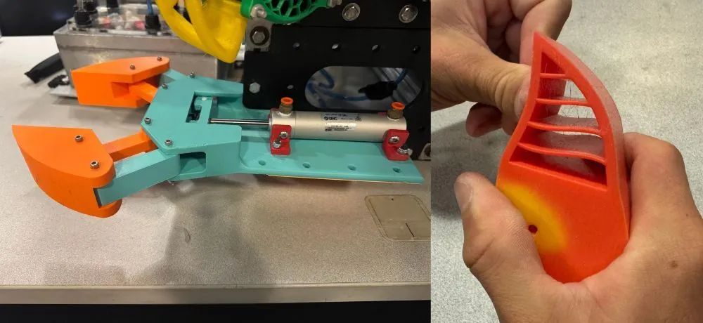
Arm assembly & adaptive claw
Dropper
This sub assembly consists of a release mechanism by a pneumatic actuator, two dropper items shaped like torpedoes, and a 3D printed housing. These dropper items are made of aluminum to ensure that they sink, and are designed such that they can be manufactured from a rectangular piece of stock using a CNC milling machine and a lathe.
A large portion of our work in this design cycle was to improve the dropper mounting mechanism and upgrade our torpedo geometry for increased accuracy. Our mounting was certified using ANSYS Mechanical and resisted double the stress factors as previous years. It included increased surface area, larger fillets, and direct chassis attachment.
Our dropper test was simple, consisting primarily of actuating the pneumatics and making sure tolerances worked as planned. Torpedo shapes were tested using the ANSYS and test rig duo, as mentioned above.
A large portion of our work in this design cycle was to improve the dropper mounting mechanism and upgrade our torpedo geometry for increased accuracy. Our mounting was certified using ANSYS Mechanical and resisted double the stress factors as previous years. It included increased surface area, larger fillets, and direct chassis attachment.
Our dropper test was simple, consisting primarily of actuating the pneumatics and making sure tolerances worked as planned. Torpedo shapes were tested using the ANSYS and test rig duo, as mentioned above.
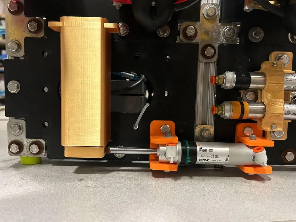
Dropper assembly
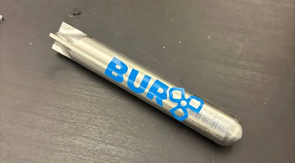
Our BUR-branded dropper item
Electronics: Hardware Systems
Battery Management System
In redesigning our onboard power management system this year, our goal was to address issues with our previous power supply system while maintaining existing modes of functionality and failure conditions. The key issues we attempted to address this year were a lack of emergency access and voltage monitoring.
To monitor battery voltage, each cell of our 4S batteries is connected using the existing voltage monitoring pins for balance charging to the ESP32. The system also has a voltage divider and low pass filter to modulate and smooth out the incoming battery voltage reading, as well as a zener diode to clamp the incoming signal. When a cell reading drops below the nominal 3.7V threshold, the system emergency shutoff is triggered. Our other major modification this year was making our emergency shutoff much easier to access, as our previous switch was difficult to handle dexterously underwater in case of an emergency. Our solution to this issue was a magnetic contact sensor, backed by a panel of magnetic material, soldered in line with our existing switch structure to control our primary relay. This allowed us to attach a strong magnet to the exterior of our battery enclosure, actuating the switch across the barrier and attracting the magnetic panel material. With a 3D-printed handle attached to the magnet, we can now easily grasp and remove the magnet to deactivate the robot, increasing safety and efficiency in shutdown and startup.
To monitor battery voltage, each cell of our 4S batteries is connected using the existing voltage monitoring pins for balance charging to the ESP32. The system also has a voltage divider and low pass filter to modulate and smooth out the incoming battery voltage reading, as well as a zener diode to clamp the incoming signal. When a cell reading drops below the nominal 3.7V threshold, the system emergency shutoff is triggered. Our other major modification this year was making our emergency shutoff much easier to access, as our previous switch was difficult to handle dexterously underwater in case of an emergency. Our solution to this issue was a magnetic contact sensor, backed by a panel of magnetic material, soldered in line with our existing switch structure to control our primary relay. This allowed us to attach a strong magnet to the exterior of our battery enclosure, actuating the switch across the barrier and attracting the magnetic panel material. With a 3D-printed handle attached to the magnet, we can now easily grasp and remove the magnet to deactivate the robot, increasing safety and efficiency in shutdown and startup.
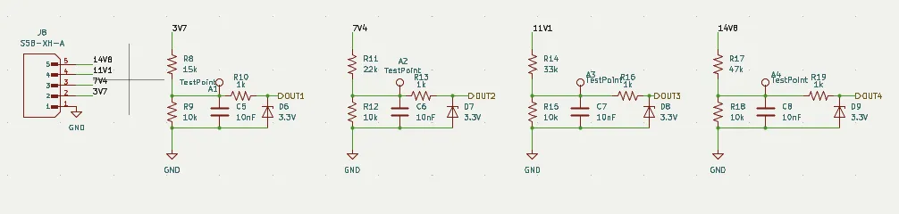
A diagram of our battery monitoring system
Emergency Shutoff
Our other major modification this year was making our emergency shutoff much easier to access, as our previous switch was difficult to handle dexterously underwater in case of an emergency. Our solution to this issue was a magnetic contact sensor, backed by a panel of magnetic material, soldered in line with our existing switch structure to control our primary relay. This allowed us to attach a strong magnet to the exterior of our battery enclosure, actuating the switch across the barrier and attracting the magnetic panel material. With a 3D-printed handle attached to the magnet, we can now easily grasp and remove the magnet to deactivate the robot, increasing safety and efficiency in shutdown and startup.
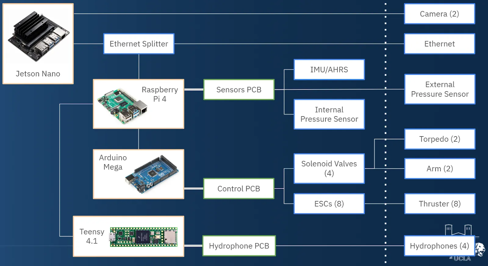
Electronics Functional Block Diagram (unchanged)
Electronics: Software Systems
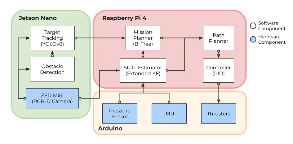
2025-2026 Software Subsystem Diagram
Goals
For our onboard software, our focus this year was primarily on improving aspects of our existing subsystems, particularly our object detection models.
For our robot controller, we had previously been relying on velocity control, which required additional complexity in other subsystems to achieve proper positioning. This year, we moved to using cascaded position-velocity PID controllers, keeping in place our existing design of assigning an independent controller to each degree of freedom of our robot. To test the real-life performance of our controller, we did pool testing in order to gather performance data and tune our controller parameters accordingly. To test, we would disturb our robot (either via a physical push, or by attaching additional buoyant material), then record our robot’s position and orientation error as it attempted to return to steady state.
For our robot controller, we had previously been relying on velocity control, which required additional complexity in other subsystems to achieve proper positioning. This year, we moved to using cascaded position-velocity PID controllers, keeping in place our existing design of assigning an independent controller to each degree of freedom of our robot. To test the real-life performance of our controller, we did pool testing in order to gather performance data and tune our controller parameters accordingly. To test, we would disturb our robot (either via a physical push, or by attaching additional buoyant material), then record our robot’s position and orientation error as it attempted to return to steady state.
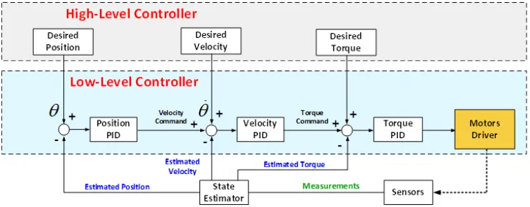
Control diagram for a cascaded PID controller [1]
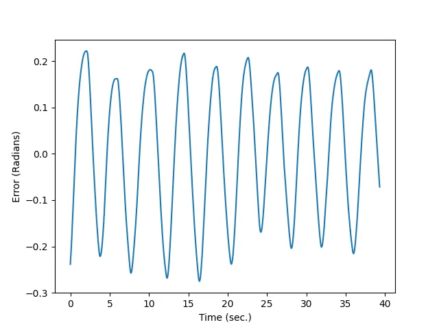
An example underdamped error curve observed during testing
Vision
For our vision software, building on last year's simulation pipeline, this year's efforts focused on aligning our synthetic training data with real-life conditions to better prepare the model for real-life competition conditions. On the rendering side, the Unity environment was enhanced with reverse projection caustics to produce the flickering light patterns characteristic of real underwater environments. Water clarity was also increased to better reflect competition water conditions.
To further close the gap between synthetic and real data, we experimented with Fast Fourier Transform (FFT)-based domain adaptation. By replacing the lower-order frequencies in our synthetic images with the lower-order frequencies of real competition images, we can better align the underlying color distribution of our synthetic images with the actual underwater footage [3]. By aligning our synthetic data with real data, we thereby reduce the visual shift the model would otherwise experience at competition.
This year, we trained our main vision model to identify the gate, bin, slalom, and tagging elements. In addition, we are developing a dedicated secondary model specifically for the torpedo task. This model operates exclusively within the torpedo target's bounding box as identified by the primary tagging detector, treating the cropped region as its input. This way, the secondary model can focus on the fine-grained spatial detail needed to reliably localize individual holes.
For vision testing, our testing set was kept entirely separate from both training and validation data, drawing primarily from video footage and images captured at last year's competition. Given that the core game elements have remained largely consistent between years (with exceptions), this footage provided us a strong real-world benchmark for evaluating model performance.
To further close the gap between synthetic and real data, we experimented with Fast Fourier Transform (FFT)-based domain adaptation. By replacing the lower-order frequencies in our synthetic images with the lower-order frequencies of real competition images, we can better align the underlying color distribution of our synthetic images with the actual underwater footage [3]. By aligning our synthetic data with real data, we thereby reduce the visual shift the model would otherwise experience at competition.
This year, we trained our main vision model to identify the gate, bin, slalom, and tagging elements. In addition, we are developing a dedicated secondary model specifically for the torpedo task. This model operates exclusively within the torpedo target's bounding box as identified by the primary tagging detector, treating the cropped region as its input. This way, the secondary model can focus on the fine-grained spatial detail needed to reliably localize individual holes.
For vision testing, our testing set was kept entirely separate from both training and validation data, drawing primarily from video footage and images captured at last year's competition. Given that the core game elements have remained largely consistent between years (with exceptions), this footage provided us a strong real-world benchmark for evaluating model performance.
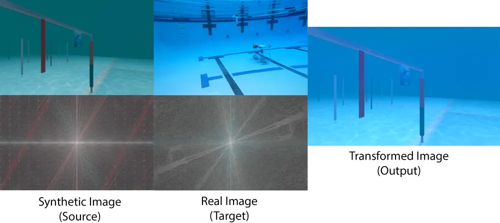
Fourier domain adaptation in action
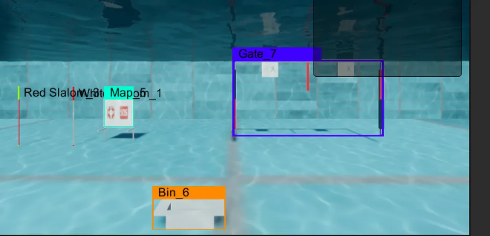
A synthetic image from our dataset (with labels)
Other Improvements
Another subject of testing was our behavior tree-based mission manager. To test it, we used a series of prespecified inputs to ensure that the output behaviors matched our expectations. We tested several tasks/missions – for each mission, a prewritten set of inputs were provided, and the resulting commands from the mission manager were compared to our expectation. We also did some exploratory work integrating the Gazebo simulation suite into our testing process for proper physical simulation, though we have not yet incorporated simulated game objects.
Outside of these changes, another new addition this year was the integration of Docker, a software virtualization platform, into our testing framework. This has helped us greatly by allowing us to conduct any purely-software tests within a highly reproducible closed development environment. Notably, we did some exploratory work this year to integrate Gazebo, a physical simulation, into our testing process.
Outside of these changes, another new addition this year was the integration of Docker, a software virtualization platform, into our testing framework. This has helped us greatly by allowing us to conduct any purely-software tests within a highly reproducible closed development environment. Notably, we did some exploratory work this year to integrate Gazebo, a physical simulation, into our testing process.
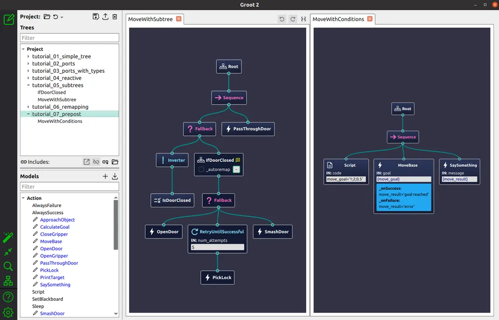
Groot, a BehaviorTree.CPP visualizer [2]
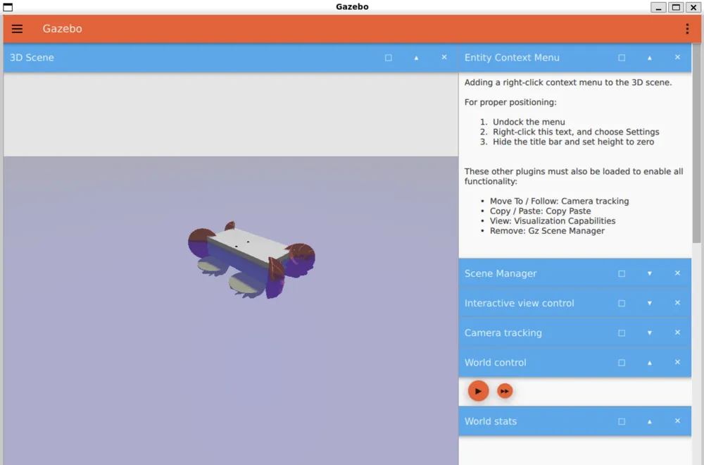
An image of our simulated robot in Gazebo
References
[1] A. M. El-Dalatony, T. Attia, H. Ragheb, and A. M. Sharaf, “Cascaded pid trajectory tracking control for quadruped robotic leg,” International Journal of Mechanical Engineering and Robotics Research, vol. 12, no. 1, pp. 40–47, Jan. 2023.
[2] “Groot2 | BehaviorTree.CPP.” Accessed: May 28, 2026. [Online]. Available: https://www.behaviortree.dev/groot/
[3] Y. Yang and S. Soatto, “FDA: Fourier Domain Adaptation for Semantic Segmentation,” presented at the Proceedings of the IEEE/CVF Conference on Computer Vision and Pattern Recognition, 2020, pp. 4085–4095. Accessed: May 26, 2026. [Online].
[2] “Groot2 | BehaviorTree.CPP.” Accessed: May 28, 2026. [Online]. Available: https://www.behaviortree.dev/groot/
[3] Y. Yang and S. Soatto, “FDA: Fourier Domain Adaptation for Semantic Segmentation,” presented at the Proceedings of the IEEE/CVF Conference on Computer Vision and Pattern Recognition, 2020, pp. 4085–4095. Accessed: May 26, 2026. [Online].